The plan
This article shows how to create particle effects using only fragment shaders.
Why? When you try to create particle system that runs in a single full-screen draw, you notice that such a constraint force you to figure out some unconventional rendering techniques. It improves shader programming skills and unlocks a new way of thinking about shader programming.
In this article I make easy to follow case study of implementing such particles.
By the end of this article, you will learn:
The origin of the idea.
Exploring the original ShaderToy shader that I will modify.
Implementing fragment-shader particles in Unity.
Implementing grid-based instancing of simple shapes.
Rendering the particles on a 3D plane.
Using many moving planes to fake dense 3D particle fields.
Integrating custom particles with a ShaderToy shader.
Profiling the created particles and doing a few optimization iterations.
___
The origin of the idea
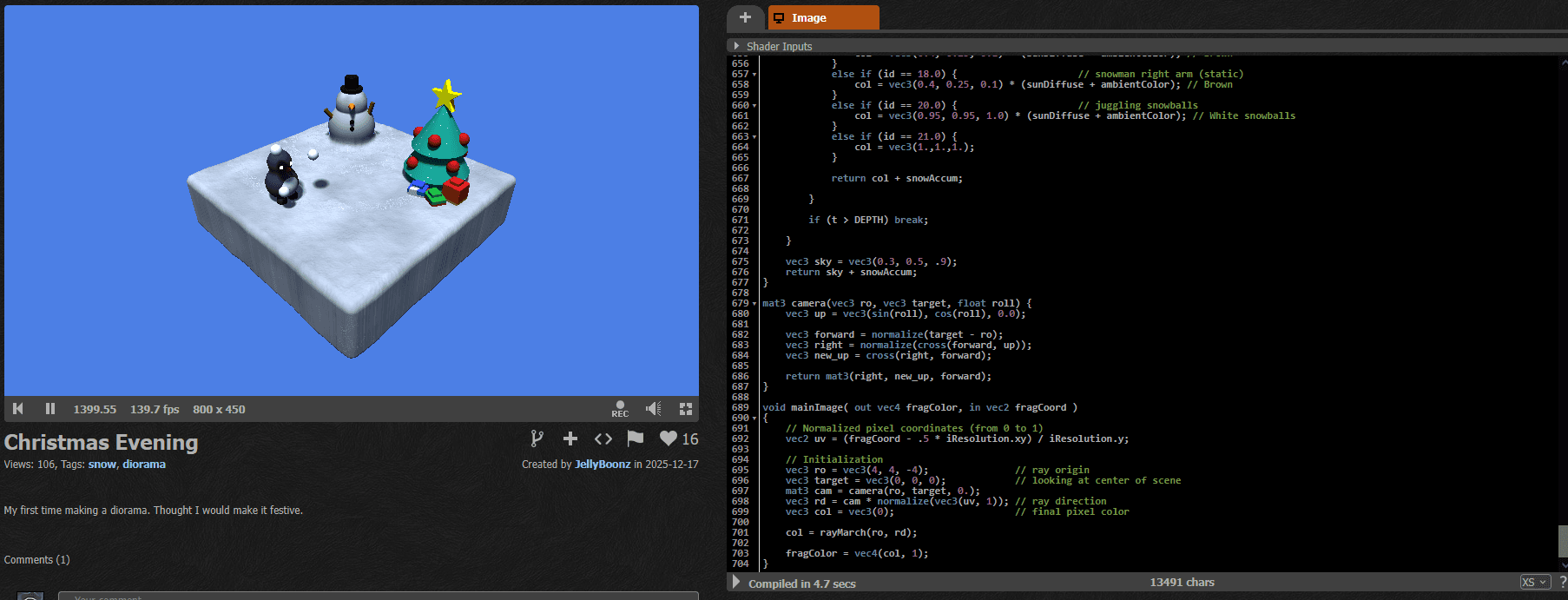
When browsing LinkedIn, I saw the shader made by Jaiden Ortiz. He created this Christmas diorama to practice SDF modelling, raymarching, lighting and simple animation.
https://www.shadertoy.com/view/wfKcDK
I really think that when you learn graphics programming, you should separate shader programming and coding with graphics APIs, so for me this shader is a textbook example of the learning process that happens when you explore what's possible with fragment shaders. I love it!
However, it has a small issue. The snow particles glitch and stop after a while. So I asked Jaiden if I could fix that.
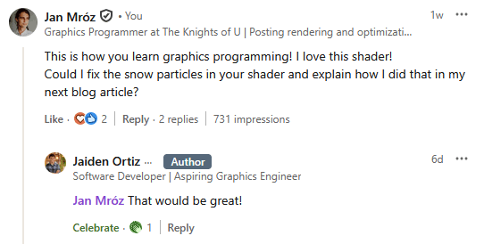
So this blog article documents the whole process of fixing and optimizing the fragment shader particles!
___
Understanding ShaderToy rendering
The shader is implemented on ShaderToy, which is a platform for coding only fullscreen fragment shaders. For me it is the best platform to learn shader programming, because with this constraint, you need to think really creatively to implement anything.
This is how ShaderToy looks. On the left, you can see how your shader looks when rendered fullscreen. On the right, there is the source code. The void mainImage( out vec4 fragColor, in vec2 fragCoord ) is the entry point of the fragment shader and it is invoked for each pixel of the image.
___
Usual 3D rendering path in ShaderToy
Usually, to render 3D scenes in a fullscreen shader you need to:
Define a camera. Usually by defining a ray for each pixel and transforming it with a matrix.
Trace the scene. Here you will see ray tracing or ray marching.
Color the results. Results returned by tracing the scene are colored using some lighting algorithms.
___
Define a camera
In this shader, the camera is defined by a per-pixel ray and the matrix that translates the ray direction.
The ray is created using screen UV and the camera matrix is defined by ray origin and look-at position.
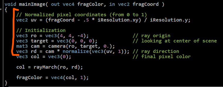
ro - ray origin
rd - ray direction
cam - camera matrix
___
Trace the scene and color the results
Then, after the ray direction and ray origin are created, the 3D scene is raymarched and colored in the rayMarch(ro, rd) function.

The rayMarch function traces the scene by using a classic SDF raymarching algorithm. The scene is defined by an SDF (signed distance field). It is a function that for each point in 3D space can return the distance to the closest surface. And the distance is signed, so if you are inside the object, the distance is negative.
Raymarching works by marching along the ray, sampling the field, and making small steps forward as long as the surface is not hit. This is a 2D visualization.
Source (interactive shader): https://www.shadertoy.com/view/4lyBDV
So here, the scene is modeled with some simple shapes, like spheres, cones, and cubes. And the scene is colored depending on which object was hit.

___
Implementing the particles
Now that I understand how the original shader works, I can create better snow particles. The original particles had a bug where they glitched after a while. They also had some visual artifacts.
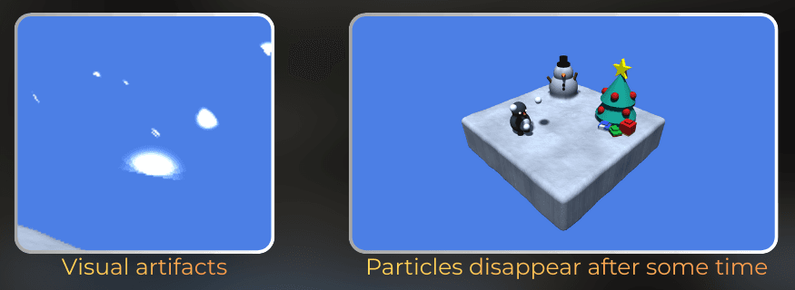
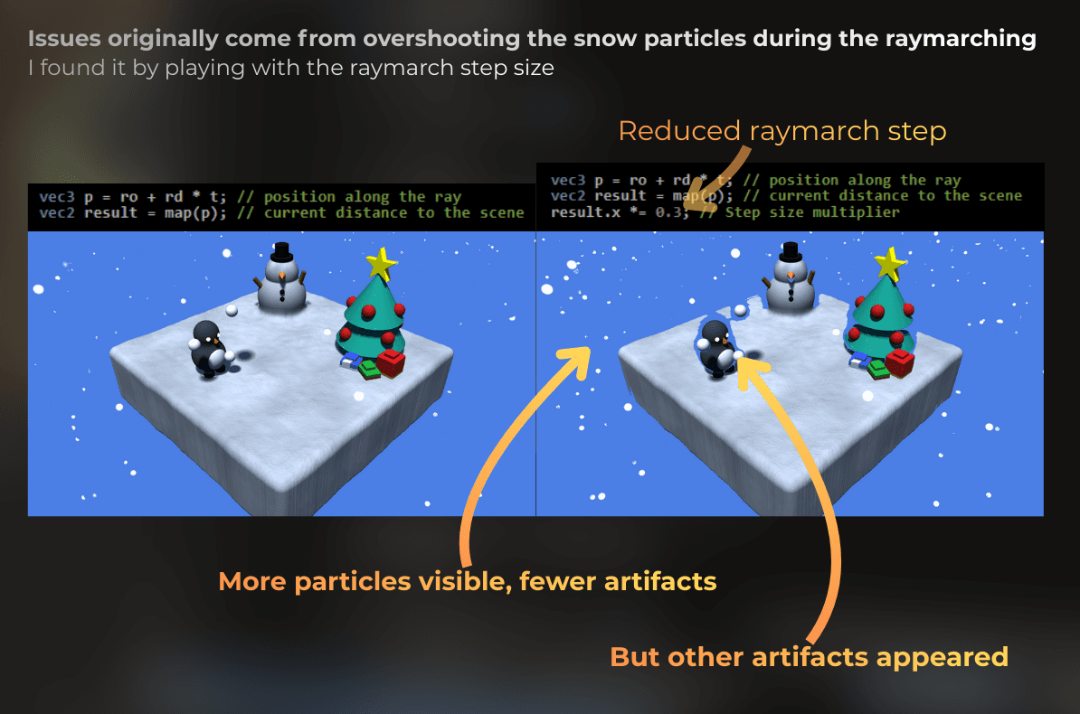
Here I will create a new particle system from scratch that avoids the issues. I will decouple particles from raymarching and use non-raymarching technique to avoid artifacts.
Let's implement the nice-looking particles first, without the 3D scene, and then I will think about how to integrate them with the shader.
I will implement this in HLSL in Unity, just to be able to profile the particles and iterate on optimization. After the particles are done, I will port them into GLSL and ShaderToy.
___
Initial setup
I'm using Unity 6000.2.9f1 with the URP render pipeline. I created this component to render a fullscreen transparent draw (just two triangles, using a material):
This script hooks into Unity's render pipeline. The RenderPipelineManager.beginCameraRendering event fires before each camera renders. We use it to draw our fullscreen effect. The Graphics.RenderPrimitives call renders 6 vertices as triangles, which makes 2 triangles that cover the screen.
[ExecuteAlways]
public class ProceduralRenderer : MonoBehaviour
{
public Material material;
private void OnEnable()
{
RenderPipelineManager.beginCameraRendering += RenderPipelineManager_beginCameraRendering;
}
private void OnDisable()
{
RenderPipelineManager.beginCameraRendering -= RenderPipelineManager_beginCameraRendering;
}
private void RenderPipelineManager_beginCameraRendering(ScriptableRenderContext context, Camera camera)
{
bool isGoodCamera = camera.cameraType == CameraType.Game;
isGoodCamera |= camera.cameraType == CameraType.SceneView;
if (!isGoodCamera || material == null)
return;
RenderParams renderParams = new RenderParams()
{
camera = camera,
material = material,
worldBounds = new Bounds(Vector3.zero, Vector3.one * 10000.0f),
};
Graphics.RenderPrimitives(renderParams, MeshTopology.Triangles, 6, 1);
Then I created a shader that draws a fullscreen rectangle:
Shader "ProceduralPixels/FragmentShaderParticles-Blog"
{
SubShader
{
Tags
{
"RenderType" = "Transparent"
"IgnoreProjector" = "True"
"RenderPipeline" = "UniversalPipeline"
}
Pass
{
Name "ForwardLit"
Tags
{
"LightMode" = "UniversalForwardOnly"
}
Cull Off
ZWrite Off
ZTest Off
Blend SrcAlpha OneMinusSrcAlpha
HLSLPROGRAM
#pragma vertex vert
#pragma fragment frag
#include "Packages/com.unity.render-pipelines.universal/ShaderLibrary/Core.hlsl"
static float2 quadUVs[] =
{
float2(0.0f, 0.0f), float2(0.0f, 1.0f), float2(1.0f, 1.0f),
float2(0.0f, 0.0f), float2(1.0f, 1.0f), float2(1.0f, 0.0f)
};
struct FragmentData
{
float4 positionCS : SV_Position;
float2 uv : TEXCOORD0;
};
FragmentData vert(uint vertexID : SV_VertexID)
{
FragmentData output;
output.positionCS = float4(quadUVs[vertexID] * 2.0 - 1.0, 0.5, 1.0);
output.uv = quadUVs[vertexID];
#if UNITY_UV_STARTS_AT_TOP
output.uv.y = 1.0 - output.uv.y;
#endif
return output;
}
float4 frag(FragmentData input) : SV_Target0
{
return float4(input.uv.xy, 0.0, 1.0);
}
ENDHLSL
This is how it looks in Unity:

___
Drawing particles
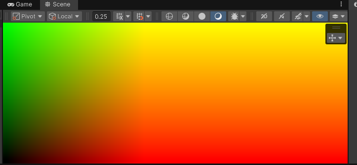
Let's draw some particles in fullscreen first. From now on, I will be modifying the fragment shader only.
I will create a UV that is screen aspect-ratio agnostic:
float2 uv = input.uv.xy;
uv.x *= _ScreenParams.x / _ScreenParams.y;
return float4(pow(uv.xy, 2.0), 0.0, 1.0
float2 uv = input.uv.xy;
uv.x *= _ScreenParams.x / _ScreenParams.y;
return float4(pow(uv.xy, 2.0), 0.0, 1.0
float2 uv = input.uv.xy;
uv.x *= _ScreenParams.x / _ScreenParams.y;
return float4(pow(uv.xy, 2.0), 0.0, 1.0
Then, I will use a fractional part to divide the space into a grid.
Using a fractional part splits continuous UV space into repeating 0-1 cells, while integer part represents the ID of the created cell.
uv *= 4.0;
float2 cellID = floor(uv);
float2 cellUV = uv - floor(uv);
return float4(cellUV.xy, 0.0, 1.0
uv *= 4.0;
float2 cellID = floor(uv);
float2 cellUV = uv - floor(uv);
return float4(cellUV.xy, 0.0, 1.0
uv *= 4.0;
float2 cellID = floor(uv);
float2 cellUV = uv - floor(uv);
return float4(cellUV.xy, 0.0, 1.0

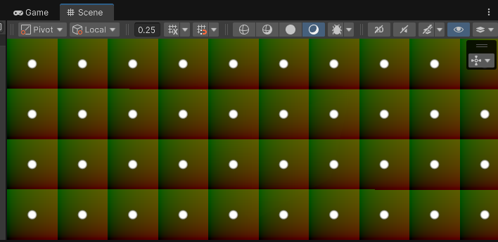
Now, using the cellUV, I will draw a disk at the center of each grid cell:
The DrawDisk function uses smoothstep to create a smooth falloff. It fades from 1.0 to 0.0 as the distance goes from diskRadius * 0.5 to diskRadius. This creates a soft edge on the particle.
float DrawDisk(float2 uv, float2 diskCenter, float diskRadius)
{
	float distanceToCenter = distance(uv, diskCenter);
	return smoothstep(diskRadius, diskRadius * 0.5, distanceToCenter);
}

float4 frag(FragmentData input) : SV_Target0
{
	...
	float disk = DrawDisk(cellUV, float2(0.5, 0.5), 0.1);
	return float4((float3)disk, 1.0) + float4(cellUV.xy, 0.0, 1.0) * 0.1
Now, I will animate the position of each point using sine waves:
float2 diskCenter = cos(_Time.yy * float2(2.0, 5.3)) * 0.5 + 0.5;
float disk = DrawDisk(cellUV, diskCenter, 0.1
float2 diskCenter = cos(_Time.yy * float2(2.0, 5.3)) * 0.5 + 0.5;
float disk = DrawDisk(cellUV, diskCenter, 0.1
float2 diskCenter = cos(_Time.yy * float2(2.0, 5.3)) * 0.5 + 0.5;
float disk = DrawDisk(cellUV, diskCenter, 0.1
The particles now move in circles. All particles move in sync because they use the same time value.
Now, each point in each grid cell moves in the same way. So I will use a hash function on cell ID to randomize it:
The FastHash2_2 function takes a 2D input and returns a random-looking 2D output. This is a deterministic hash that always returns the same output for the same input. I'm using a simple integer-based hash function (implementation not shown, but any 2D hash will work).
float2 cellIDHash = FastHash2_2(cellID);
float2 diskCenter = cos(_Time.yy * cellIDHash * 5.0) * 0.5 + 0.5;
float2 cellIDHash = FastHash2_2(cellID);
float2 diskCenter = cos(_Time.yy * cellIDHash * 5.0) * 0.5 + 0.5;
float2 cellIDHash = FastHash2_2(cellID);
float2 diskCenter = cos(_Time.yy * cellIDHash * 5.0) * 0.5 + 0.5;
Now each particle moves at a different speed and direction, creating natural variation.
Now I need to fix the issue with the boundaries and keep each disk within its cell bounds:
float2 cellIDHash = FastHash2_2(cellID);
float2 diskCenter = cos(_Time.yy * cellIDHash * 5.0) * 0.5 + 0.5;
diskCenter = lerp(DiskRadius, 1.0 - DiskRadius, diskCenter);
float disk = DrawDisk(cellUV, diskCenter, DiskRadius
float2 cellIDHash = FastHash2_2(cellID);
float2 diskCenter = cos(_Time.yy * cellIDHash * 5.0) * 0.5 + 0.5;
diskCenter = lerp(DiskRadius, 1.0 - DiskRadius, diskCenter);
float disk = DrawDisk(cellUV, diskCenter, DiskRadius
float2 cellIDHash = FastHash2_2(cellID);
float2 diskCenter = cos(_Time.yy * cellIDHash * 5.0) * 0.5 + 0.5;
diskCenter = lerp(DiskRadius, 1.0 - DiskRadius, diskCenter);
float disk = DrawDisk(cellUV, diskCenter, DiskRadius
And now, let's make the UV scroll.
Looks like snow to me!
And this is the full shader code till now:
float DrawDisk(float2 uv, float2 diskCenter, float diskRadius)
{
	float distanceToCenter = distance(uv, diskCenter);
	return smoothstep(diskRadius, diskRadius * 0.5, distanceToCenter);
}

static float DiskRadius = 0.1;

float4 frag(FragmentData input) : SV_Target0
{
	float2 uv = input.uv.xy;
	uv.x *= _ScreenParams.x / _ScreenParams.y;

	uv *= 4.0;
	uv.y += _Time.y * 1.5;

	float2 cellID = floor(uv);
	float2 cellUV = uv - floor(uv);

	float2 cellIDHash = FastHash2_2(cellID);
	float2 diskCenter = cos(_Time.yy * cellIDHash * 2.0) * 0.5 + 0.5;
	diskCenter = lerp(DiskRadius, 1.0 - DiskRadius, diskCenter);
	float disk = DrawDisk(cellUV, diskCenter, DiskRadius);

	return float4((float3)disk, 1.0
___
Making it render on a 3D plane
Now I have nice snow particles that work in 2D, but I need to make them work in 3D.
Why do we need 3D? The ShaderToy shader renders a 3D scene using raymarching. To integrate our particles with that scene, they need to exist in the same 3D space. Otherwise, they would just be a flat overlay that doesn't interact with the 3D objects.
In a ShaderToy shader, the rendering uses raymarching and each pixel has a ray that goes from the camera towards the scene. I will recreate this setup in Unity and I will render those particles on a 3D plane.
___
Ray origin and direction
To create the ray origin and ray direction of the camera for each pixel, I will:
Modify the vertex shader to include a world space position.
Use the world space position and camera position in the fragment shader to reconstruct the ray origin and ray direction.
So, let's start by modifying the interpolators:
struct FragmentData
{
float4 positionCS : SV_Position;
float2 uv : TEXCOORD0;
float4 positionWS : TEXCOORD1;
struct FragmentData
{
float4 positionCS : SV_Position;
float2 uv : TEXCOORD0;
float4 positionWS : TEXCOORD1;
struct FragmentData
{
float4 positionCS : SV_Position;
float2 uv : TEXCOORD0;
float4 positionWS : TEXCOORD1;
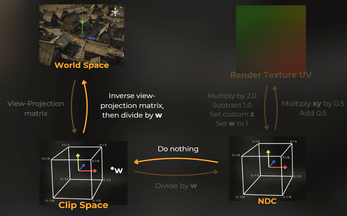
But how can I get the world space position in a fullscreen draw? Well, I have a clip space position that creates a fullscreen triangle, so I can use an inverse view-projection matrix to reconstruct the world space position. According to the image below, I will move from NDC into a world space.
FragmentData vert(uint vertexID : SV_VertexID)
{
FragmentData output;
output.positionCS = float4(quadUVs[vertexID] * 2.0 - 1.0, 0.5, 1.0);
output.uv = quadUVs[vertexID];
output.positionWS = mul(UNITY_MATRIX_I_VP, output.positionCS);
output.positionWS /= output.positionWS.w
FragmentData vert(uint vertexID : SV_VertexID)
{
FragmentData output;
output.positionCS = float4(quadUVs[vertexID] * 2.0 - 1.0, 0.5, 1.0);
output.uv = quadUVs[vertexID];
output.positionWS = mul(UNITY_MATRIX_I_VP, output.positionCS);
output.positionWS /= output.positionWS.w
FragmentData vert(uint vertexID : SV_VertexID)
{
FragmentData output;
output.positionCS = float4(quadUVs[vertexID] * 2.0 - 1.0, 0.5, 1.0);
output.uv = quadUVs[vertexID];
output.positionWS = mul(UNITY_MATRIX_I_VP, output.positionCS);
output.positionWS /= output.positionWS.w
And then I can use it in the fragment shader to recreate the ray direction and ray origin:
float4 frag(FragmentData input) : SV_Target0
{
float3 rayOriginWS = _WorldSpaceCameraPos.xyz;
float3 rayDirectionWS = normalize(input.positionWS.xyz - rayOriginWS.xyz);
return float4((rayDirectionWS), 1.0
float4 frag(FragmentData input) : SV_Target0
{
float3 rayOriginWS = _WorldSpaceCameraPos.xyz;
float3 rayDirectionWS = normalize(input.positionWS.xyz - rayOriginWS.xyz);
return float4((rayDirectionWS), 1.0
float4 frag(FragmentData input) : SV_Target0
{
float3 rayOriginWS = _WorldSpaceCameraPos.xyz;
float3 rayDirectionWS = normalize(input.positionWS.xyz - rayOriginWS.xyz);
return float4((rayDirectionWS), 1.0
It looks like it works correctly, because the ray direction colors reflect the colors of the world space coordinate handles:
___
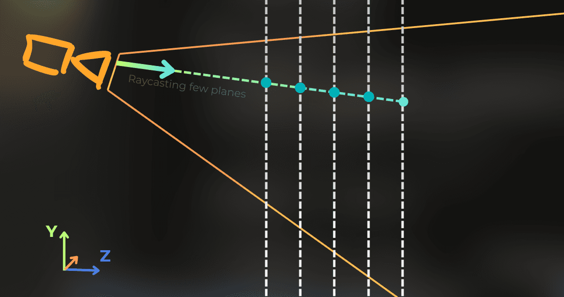
Raycasting a plane
Now I will use raycasting to hit a plane in 3D. I will create a function based on this infographic:

This is the function that does the plane raycast.
The math here is based on the plane equation. A plane is defined by a normal vector and a distance from the origin (offset). The function calculates how far along the ray we need to travel to hit the plane. It returns the distance t, where hitPosition = rayOrigin + rayDirection * t.
float RaycastPlane(float3 rayOrigin, float3 rayDirection, float3 planeNormal, float offset)
{
return (offset - dot(planeNormal, rayOrigin)) / dot(planeNormal, rayDirection
float RaycastPlane(float3 rayOrigin, float3 rayDirection, float3 planeNormal, float offset)
{
return (offset - dot(planeNormal, rayOrigin)) / dot(planeNormal, rayDirection
float RaycastPlane(float3 rayOrigin, float3 rayDirection, float3 planeNormal, float offset)
{
return (offset - dot(planeNormal, rayOrigin)) / dot(planeNormal, rayDirection
And I used it to raycast the Z plane in world space:
float4 frag(FragmentData input) : SV_Target0
{
float3 rayOriginWS = _WorldSpaceCameraPos.xyz;
float3 rayDirectionWS = normalize(input.positionWS.xyz - rayOriginWS.xyz);
float hitT = RaycastPlane(rayOriginWS.xyz, rayDirectionWS.xyz, float3(0.0, 0.0, 1.0), 0.0);
float3 hitPositionWS = rayOriginWS.xyz + rayDirectionWS.xyz * hitT;
float2 uv = hitPositionWS.xy;
uv.y += _Time.y * 1.5;
float2 cellID = floor(uv);
float2 cellUV = uv - floor(uv
From the side, it looks like this:

___
Making it volumetric
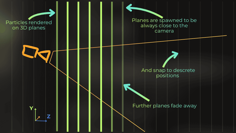
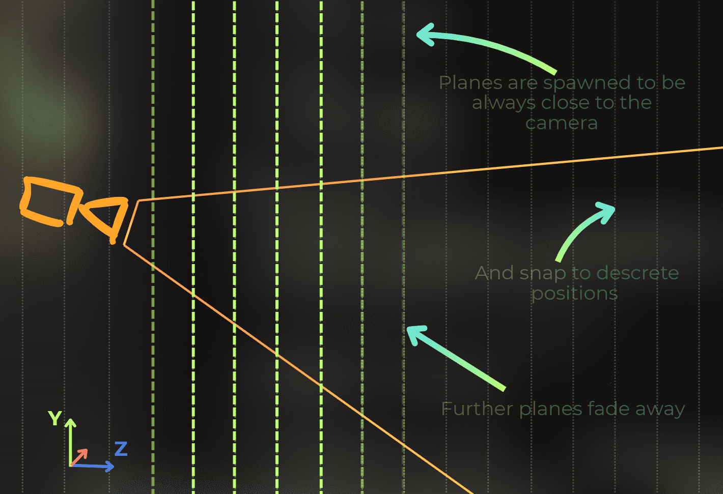
Now, all the particles fall on a flat surface. To make it 3D, I will create multiple planes with the particles, each plane will be positioned using a different offsets.
I will create a for loop in the shader code where I will iterate a few times to render many layers of those particles:
const static float LayersCount = 10.0;
const static float DistanceBetweenLayers = 1.0;
float4 frag(FragmentData input) : SV_Target0
{
float3 rayOriginWS = _WorldSpaceCameraPos.xyz;
float3 rayDirectionWS = normalize(input.positionWS.xyz - rayOriginWS.xyz);
float sum = 0.0;
for (float i = 0.0; i < LayersCount; i++)
{
float planeOffset = i * DistanceBetweenLayers;
float hitT = RaycastPlane(rayOriginWS.xyz, rayDirectionWS.xyz, float3(0.0, 0.0, 1.0), planeOffset);
if (hitT < 0.0)
continue;
float3 hitPositionWS = rayOriginWS.xyz + rayDirectionWS.xyz * hitT;
float2 uv = hitPositionWS.xy;
uv.y += _Time.y * 1.5;
float2 cellID = floor(uv);
float2 cellUV = uv - floor(uv);
float2 cellIDHash = FastHash2_2(cellID);
float2 diskCenter = cos(_Time.yy * cellIDHash * 2.0) * 0.5 + 0.5;
diskCenter = lerp(DiskRadius, 1.0 - DiskRadius, diskCenter);
float disk = DrawDisk(cellUV, diskCenter, DiskRadius);
sum += disk;
}
return float4((float3)sum, 1.0
Now each layer looks the same, so I will include the layer ID in the cellIDHash calculation to make each layer unique:
float2 cellIDHash = FastHash2_2(cellID * 13.8974 + i * 7.39712
float2 cellIDHash = FastHash2_2(cellID * 13.8974 + i * 7.39712
float2 cellIDHash = FastHash2_2(cellID * 13.8974 + i * 7.39712
Nice! It is hard to notice any planes!
I have a problem that those layers are always in a fixed position, and I want to make them spawn always from the camera position. Look at what happens when I move the camera:
I will modify the loop to begin rendering from the plane that is closest to the camera. I will also snap all the planes to the distance between the layers.
This is a modified code:
float3 planeNormal = float3(0.0, 0.0, 1.0);
float startPlaneOffset = floor(dot(rayOriginWS.xyz, planeNormal) / DistanceBetweenLayers) * DistanceBetweenLayers;
for (float i = 0.0; i < LayersCount; i++)
{
float planeOffset = startPlaneOffset + i * DistanceBetweenLayers;
float hitT = RaycastPlane(rayOriginWS.xyz, rayDirectionWS.xyz, planeNormal, planeOffset);
if (hitT < 0.0)
continue;
float3 hitPositionWS = rayOriginWS.xyz + rayDirectionWS.xyz * hitT;
float2 uv = hitPositionWS.xy;
uv.y += _Time.y * 1.5;
float2 cellID = floor(uv);
float2 cellUV = uv - floor(uv);
float2 cellIDHash = FastHash2_2(cellID * 13.8974 + planeOffset * 7.39712);
float2 diskCenter = cos(_Time.yy * cellIDHash * 2.0) * 0.5 + 0.5;
diskCenter = lerp(DiskRadius, 1.0 - DiskRadius, diskCenter);
float disk = DrawDisk(cellUV, diskCenter, DiskRadius);
sum += disk
Now I will make the furthest and closest particles smoothly fade away to avoid this popping effect in the distance.
for (float i = 0.0; i < LayersCount; i++)
{
float planeOffset = startPlaneOffset + i * DistanceBetweenLayers;
...
float distanceToPlane = planeOffset - dot(planeNormal, rayOriginWS);
float alpha = smoothstep((LayersCount - 1.0) * DistanceBetweenLayers, 0.0, distanceToPlane);
alpha *= smoothstep(DistanceBetweenLayers * 0.5, DistanceBetweenLayers * 2.0, distanceToPlane);
...
sum += disk * alpha
Sweet!
___
Making it work with any rotation
Currently, I implemented it using XY planes. However, it would be nice to control the rotation of those particles to make them more aligned with specific camera angles. The original shader has a camera that is tilted a little, and it would be nice if the particles could face the camera.
To make this happen, I will use a rotation matrix. So the rendering will stay the same. I will just rotate the rayOrigin and rayDirection before the calculations happen.
This is my helper function for creating a 3D rotation matrix from euler angles:
float3x3 Get3DRotationMatrix(float3 angles)
{
	float3x3 mat = float3x3(
		1.0, 0.0, 0.0,
		0.0, 1.0, 0.0,
		0.0, 0.0, 1.0
	);

	mat = mul(float3x3(
		cos(angles.z), sin(angles.z), 0.0,
		-sin(angles.z), cos(angles.z), 0.0,
		0.0, 0.0, 1.0
	), mat);

	mat = mul(float3x3(
		1.0, 0.0, 0.0,
		0.0, cos(angles.x), sin(angles.x),
		0.0, -sin(angles.x), cos(angles.x)
	), mat);

	mat = mul(float3x3(
		cos(angles.y), 0.0, sin(angles.y),
		0.0, 1.0, 0.0,
		-sin(angles.y), 0.0, cos(angles.y)
	), mat);

	return mat
I modified the code to use a rotation matrix on ray origin and ray direction. Since rayOrigin and rayDirection are no longer world space variables, I used a PS suffix for particle space.
Coordinate space naming convention:
WS = World Space (the global 3D coordinate system)
PS = Particle Space (a local coordinate system rotated for the particles)
float3 rayOriginWS = _WorldSpaceCameraPos.xyz;
float3 rayDirectionWS = normalize(input.positionWS.xyz - rayOriginWS.xyz);
float3x3 rotationMatrix = Get3DRotationMatrix(float3(0.9, 1.1, 0.0));
float3 movementOffsetWS = float3(0.0, 1.0, 0.0) * _Time.y * 1.5;
float3 rayOriginPS = mul(rotationMatrix, rayOriginWS.xyz + movementOffsetWS);
float3 rayDirectionPS = mul(rotationMatrix, rayDirectionWS.xyz);
Notice that the particles still fall down and the layers are smoothly scrolling.
___
Particle intersection with the scene
Now the particles work as a fullscreen effect. However, I need to figure out a way to blend them with the opaque scene.
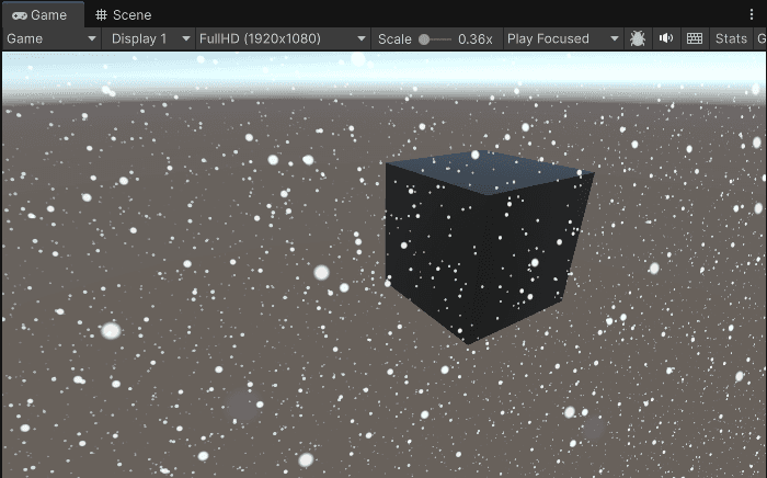
I placed a big opaque cube on the scene and modified the shader to blend with the background.
sum = clamp(sum, 0.0, 1.0);
return float4(1.0, 1.0, 1.0, sum
sum = clamp(sum, 0.0, 1.0);
return float4(1.0, 1.0, 1.0, sum
sum = clamp(sum, 0.0, 1.0);
return float4(1.0, 1.0, 1.0, sum
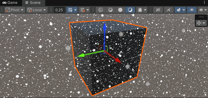
All the particle planes are rendered in a single fragment shader, so to make the particles intersect with the opaque scene content, I need to implement the depth testing in the shader. Let's do this.
I included a camera depth texture with a point clamp sampler in the shader code:
Texture2D _CameraDepthTexture;
SamplerState pointClampSampler
Texture2D _CameraDepthTexture;
SamplerState pointClampSampler
Texture2D _CameraDepthTexture;
SamplerState pointClampSampler
Then I added this code at the beginning of the fragment shader to get the distance to the scene.
distanceToSceneWS will store the distance from the camera position to the opaque surface of the scene.
float rawScreenDepth = _CameraDepthTexture.SampleLevel(pointClampSampler, input.uv, 0.0f).r;
float4 scenePositionCS = float4((input.uv.xy * 2.0 - 1.0), rawScreenDepth, 1.0);
float4 scenePositionWS = mul(UNITY_MATRIX_I_VP, scenePositionCS);
scenePositionWS /= scenePositionWS.w;
float distanceToSceneWS = distance(_WorldSpaceCameraPos.xyz, scenePositionWS);
return float4((float3)smoothstep(0.0, 20.0, distanceToSceneWS), 1.0
Visualizing the distance to scene. White areas are far from the camera, black areas are close. The cube is clearly visible as a dark silhouette.
Then I integrated it into the particle logic. The variable hitT in the loop actually contains the distance from the camera position to the particle plane, so I can just check if this distance is larger than the distance to the scene:
if (hitT < 0.0 || hitT > distanceToSceneWS)
continue
if (hitT < 0.0 || hitT > distanceToSceneWS)
continue
if (hitT < 0.0 || hitT > distanceToSceneWS)
continue
Looks good!
___
Extracting a particle rendering method
My goal was to implement the particles in the ShaderToy shader. Let's think about what is needed to fully render those particles.
Before integrating with ShaderToy, I need to organize the code. ShaderToy uses GLSL, and the particle logic is currently mixed with Unity-specific code. I will extract the particle rendering into a clean function that only needs basic inputs. This will make the port to GLSL much easier.
Looking at the source code:
I need a ray origin and ray direction.
I need a matrix to rotate the space.
I need a distance to the opaque scene.
Now, I will modify the source code and move the particle rendering logic into a separate function:
float GetFallingParticles(float3 rayOriginWS, float3 rayDirectionWS, float3x3 rotationMatrix, float distanceToSceneWS)
{
float3 movementOffsetWS = ParticleMovementOffsetWS * _Time.y * 1.5;
float3 rayOriginPS = mul(rotationMatrix, rayOriginWS.xyz + movementOffsetWS);
...
return sum;
}
float4 frag(FragmentData input) : SV_Target0
{
float rawScreenDepth = _CameraDepthTexture.SampleLevel(pointClampSampler, input.uv, 0.0f).r;
float4 scenePositionCS = float4((input.uv.xy * 2.0 - 1.0), rawScreenDepth, 1.0);
float4 scenePositionWS = mul(UNITY_MATRIX_I_VP, scenePositionCS);
scenePositionWS /= scenePositionWS.w;
float distanceToSceneWS = distance(_WorldSpaceCameraPos.xyz, scenePositionWS);
float3 rayOriginWS = _WorldSpaceCameraPos.xyz;
float3 rayDirectionWS = normalize(input.positionWS.xyz - rayOriginWS.xyz);
float3x3 rotationMatrix = Get3DRotationMatrix(float3(0.9, 1.1, 0.0));
float particles = GetFallingParticles(rayOriginWS, rayDirectionWS, rotationMatrix, distanceToSceneWS);
return float4(1.0, 1.0, 1.0, particles
I did that because it will be easier to port just the GetFallingParticles function into GLSL in ShaderToy to integrate into other shaders.
___
Fixing a precision bug
Before moving forward, I need to fix a bug I discovered. When the scene is reloaded in Unity, the particles start to pop for some reason. It looks like the randomness for each layer is messed up.
My first bet is that there is some imprecision in the hash function input that randomizes each plane. It was using a plane offset that could be a little bit different depending on the camera position. So I modified the particles and their hash function to work on the plane ID instead of the plane offset.
float startPlaneOffsetID = floor(dot(rayOriginPS.xyz, planeNormal) / DistanceBetweenLayers);
float startPlaneOffset = startPlaneOffsetID * DistanceBetweenLayers;
for (float i = 0.0; i < LayersCount; i++)
{
...
float planeID = startPlaneOffsetID + i;
float2 cellIDHash = FastHash2_2(cellID * 13.8974 + (planeID) * 7.39712
And the issue is fixed:
___
Let's integrate the particles with the diorama
Finally it's time to move the code to GLSL and use it in ShaderToy!
Now that the particles work well in Unity, I need to port them back to ShaderToy to fix the original shader. This involves converting HLSL to GLSL and removing Unity-specific code.
___
Parsing the code from HLSL to GLSL
I will go an easy way. I will use GPT o1 to parse the particles source code from HLSL into GLSL:
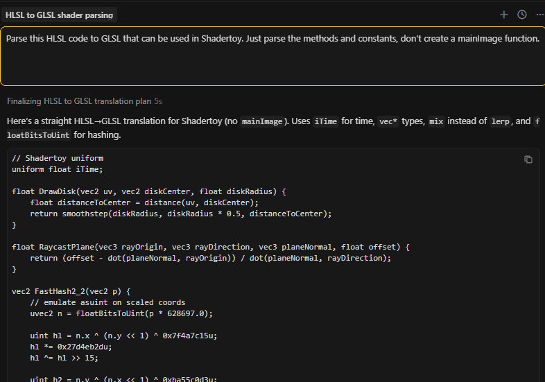
I pasted the generated code at the top of the diorama shader in ShaderToy.
___
Removing original snow particles
I removed all the snow-related code from the original shader. Basically, I removed the getSnowflake function and then removed all the code that was causing compilation issues. These are all the code fragments:

And this is how it looks now:
___
Accessing all required variables for particle rendering
Now I need to access the ray direction, ray origin, camera rotation matrix, and distance to the scene. In the code, I have access to the first three here:
ro - ray origin
rd - ray direction
cam - camera rotation matrix

For the scene distance, I need to modify the rayMarch function. I will add one more output to this function:
vec3 rayMarch(vec3 ro, vec3 rd, out float out_sceneDistance)
{
...
for (int i = 0; i < STEPS; i++)
{
vec3 p = ro + rd * t;
vec2 result = map(p);
float d = result.x;
...
t += d;
out_sceneDistance = t
vec3 rayMarch(vec3 ro, vec3 rd, out float out_sceneDistance)
{
...
for (int i = 0; i < STEPS; i++)
{
vec3 p = ro + rd * t;
vec2 result = map(p);
float d = result.x;
...
t += d;
out_sceneDistance = t
vec3 rayMarch(vec3 ro, vec3 rd, out float out_sceneDistance)
{
...
for (int i = 0; i < STEPS; i++)
{
vec3 p = ro + rd * t;
vec2 result = map(p);
float d = result.x;
...
t += d;
out_sceneDistance = t
___
Integrating the particles
Now it's time to modify the mainImage function to integrate the particles with the shader:
void mainImage( out vec4 fragColor, in vec2 fragCoord )
{
vec2 uv = (fragCoord - .5 * iResolution.xy) / iResolution.y;
vec3 ro = vec3(4, 4, -4);
vec3 target = vec3(0, 0, 0);
mat3 cam = camera(ro, target, 0.);
vec3 rd = cam * normalize(vec3(uv, 1));
vec3 col = vec3(0);
float sceneDistance = 9999.0;
col = rayMarch(ro, rd, sceneDistance);
mat3 rotationMatrix = transpose(cam);
float particles = GetFallingParticles(ro, rd, rotationMatrix, sceneDistance);
col = mix(col, vec3(1.0), particles);
fragColor = vec4(col, 1
Before:
The original shader with glitching snow particles.
Link to the original shader: https://www.shadertoy.com/view/wfKcDK
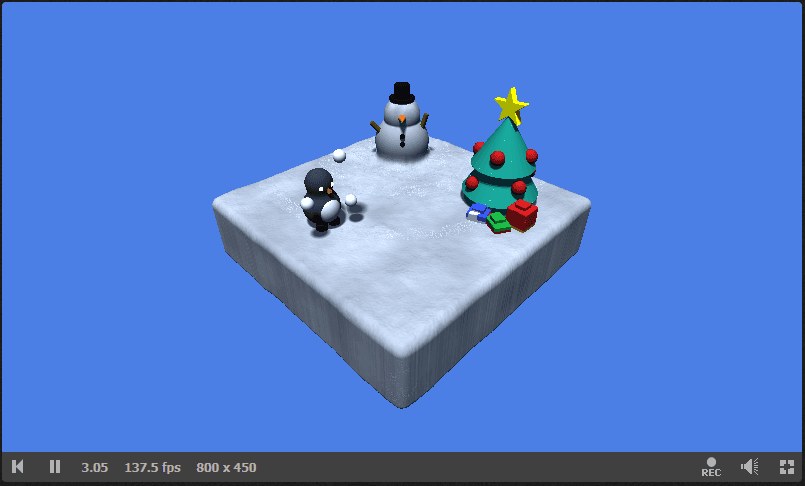
After:
The fixed shader with smooth, non-glitching snow particles that properly integrate with the 3D scene.
You can look at the modified shader here: https://www.shadertoy.com/view/WcGfDz
___
Optimization iterations
The particles work, but are they fast? Let's profile them and find out where the bottlenecks are.
I strongly believe that most of the features we implement can be easily optimized 2-3x out of the box just by opening the profiler, looking at the most important issue, and fixing it.
In this section, I will show 5 optimization iterations. Each one targets a specific bottleneck found in the profiler.
___
First profiling
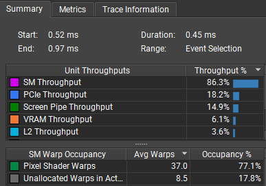
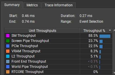
I will profile this view in a Unity application build on RTX 3060 in FullHD resolution. 20 particle layers.
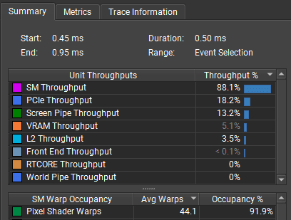
And those are the results. As expected, the shader is SM bound on the fragment shader:
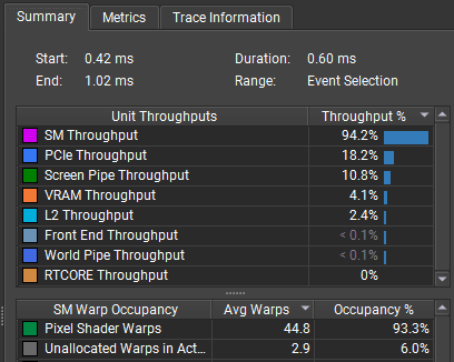
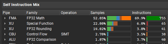
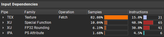
Let's look deeper and see what instructions are the most problematic:
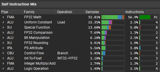
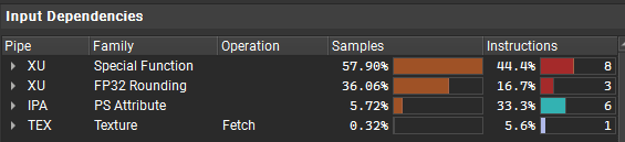
It looks like there are a few special instructions that stall the program, and the biggest issue is with the FP32 pipe, which does simple math operations. The shader also doesn't use texture fetches.
GPU terminology:
FP32 pipe: The part of the GPU that does 32-bit floating point math (add, multiply, etc.)
XU: handles special functions like sin, cos, sqrt
Texture fetches: Reading from textures, handled by dedicated texture units
Also, when looking at the shader DXIL disassembly, it contains one non-unrolled loop:
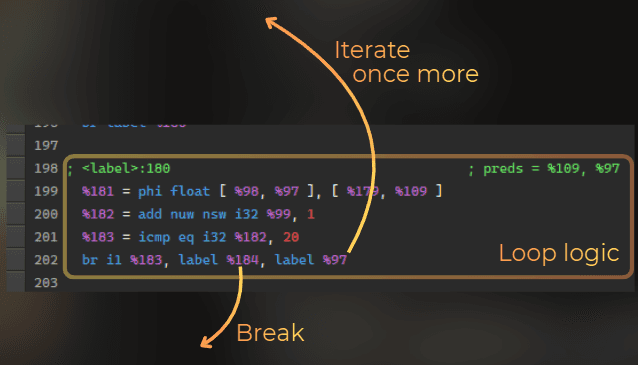
Currently I see two ways of optimizing this shader:
Loop unrolling. Could enable the compiler to do more optimizations.
Using texture samples for hash functions.
___
1st optimization iteration - loop unrolling
First of all, I added this unrolling to the particle rendering. This should strip away the loop logic from the shader and it will enable the compiler to do more optimizations. The shader was using 5-6% time on branching, so it should make it at least 5-6% faster:
[unroll]
for (float i = 0.0; i < LayersCount; i
[unroll]
for (float i = 0.0; i < LayersCount; i
[unroll]
for (float i = 0.0; i < LayersCount; i
And 0.04ms shaved (from 0.60ms to 0.56ms), as expected! Not much, but it's honest work.

___
2nd optimization iteration - using texture-based hash function
The next idea is to utilize the texturing units to speed up the hash functions. Currently the shader doesn't use textures for hash calculations, so those texture units are idle. So I used this small texture to sample a random value in the shader, instead of using an integer-based hash:
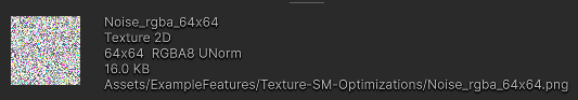
I added this function:
float2 TextureHash2_2(float2 uv)
{
	return _NoiseRGBA.SampleLevel(pointRepeatSampler, uv * 0.021, 0).rb
float2 TextureHash2_2(float2 uv)
{
	return _NoiseRGBA.SampleLevel(pointRepeatSampler, uv * 0.021, 0).rb
float2 TextureHash2_2(float2 uv)
{
	return _NoiseRGBA.SampleLevel(pointRepeatSampler, uv * 0.021, 0).rb
And added a UV offset for each particle layer:
float3 hitPositionPS = rayOriginPS.xyz + rayDirectionPS.xyz * hitT;
float2 uv = hitPositionPS.xy;
uv += planeID * 13.71;
float2 cellID = floor(uv);
float2 cellUV = uv - floor(uv);
float2 cellIDHash = TextureHash2_2(cellID + planeID * 13.489);
float2 diskCenter = cos(_Time.yy * cellIDHash * 2.0) * 0.5 + 0.5
And maybe this wasn't the best idea. The shader is a little bit faster, but I expected more. When next iterations are performed, I may actually revert these changes.
The profiler shows only marginal improvement. The shader went from 0.56ms to about 0.50ms.
And it stays at FP32 bottleneck, now together with the texture fetches:
___
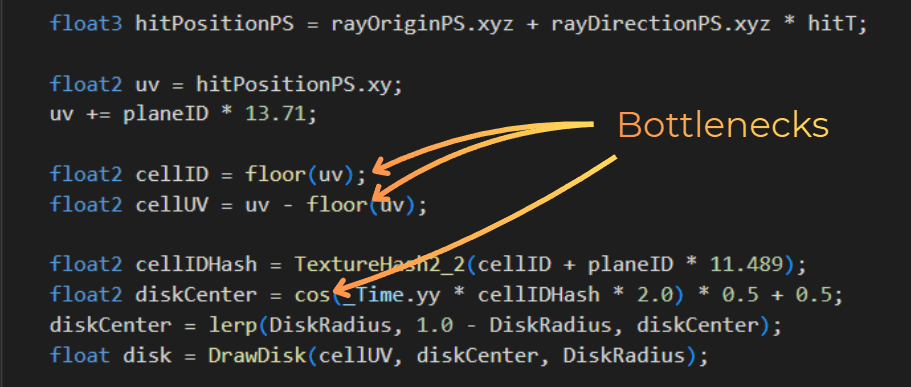
3rd optimization iteration - simplifying the shader code
Now I will focus on actual code simplification. I was able to make this code run 10% faster just by experimenting with textures and loop unrolling, which is nice, but I will not optimize anything further without modifying the shader itself.
The disk drawing uses a distance function, which involves a square root calculation. I could replace it by using a squared distance. So I replaced the DrawDisk function with this one:
float DrawDisk(float2 uv, float2 diskCenter, float diskRadius)
{
	float distanceToCenter = dot(uv - diskCenter, uv - diskCenter) - diskRadius * diskRadius;
	return smoothstep(0.0, -diskRadius * diskRadius, distanceToCenter
float DrawDisk(float2 uv, float2 diskCenter, float diskRadius)
{
	float distanceToCenter = dot(uv - diskCenter, uv - diskCenter) - diskRadius * diskRadius;
	return smoothstep(0.0, -diskRadius * diskRadius, distanceToCenter
float DrawDisk(float2 uv, float2 diskCenter, float diskRadius)
{
	float distanceToCenter = dot(uv - diskCenter, uv - diskCenter) - diskRadius * diskRadius;
	return smoothstep(0.0, -diskRadius * diskRadius, distanceToCenter
Currently, the loop raytraces each plane separately. I could simplify it and raytrace just the first and second plane, and then use the difference between the hits to calculate all other hits. I did that and also simplified some calculations from the loop (replaced smoothstep with a simple division). I did each optimization idea separately, and it was a lot of trial and error.
float3 firstHitT = RaycastPlane(rayOriginPS.xyz, rayDirectionPS.xyz, planeNormal, startPlaneOffset);
float firstPlaneDistance = startPlaneOffset - dot(planeNormal, rayOriginPS);
float3 secondHitT = RaycastPlane(rayOriginPS.xyz, rayDirectionPS.xyz, planeNormal, startPlaneOffset + DistanceBetweenLayers);
float secondPlaneDistance = (startPlaneOffset + DistanceBetweenLayers) - dot(planeNormal, rayOriginPS);
float3 hitTDelta = secondHitT - firstHitT;
float planeDistanceDelta = secondPlaneDistance - firstPlaneDistance;
float maxDistance = (LayersCount - 1.0) * DistanceBetweenLayers;
[unroll]
for (float i = 0.0; i < LayersCount; i++)
{
float planeID = startPlaneOffsetID + i;
float hitT = firstHitT + hitTDelta * i;
float distanceToPlane = firstPlaneDistance + planeDistanceDelta * i;
[flatten]
if (hitT < 0.0 || hitT > distanceToSceneWS)
continue
float alpha = clamp(1.0 - distanceToPlane / maxDistance, 0.0, 1.0);
alpha *= clamp(distanceToPlane / DistanceBetweenLayers * 2.0, 0.0, 1.0);
float3 hitPositionPS = rayOriginPS.xyz + rayDirectionPS.xyz * hitT;
float2 uv = hitPositionPS.xy;
uv += planeID * 13.71;
float2 cellID = floor(uv);
float2 cellUV = uv - floor(uv);
float2 cellIDHash = TextureHash2_2(cellID + planeID * 11.489);
float2 diskCenter = cos(_Time.yy * cellIDHash * 2.0) * 0.5 + 0.5;
diskCenter = lerp(DiskRadius, 1.0 - DiskRadius, diskCenter);
float disk = DrawDisk(cellUV, diskCenter, DiskRadius);
sum += disk * alpha
Well, it didn't get much faster at the end. It went from 0.50ms to 0.45ms. But I'm slowly getting there.
However, the bottleneck shifted completely from the FP32 to the XU. And the shader is rarely stalled.
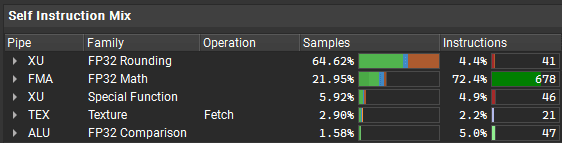
To optimize it further I would need to remove the floor() and cos() instructions and replace it with something more efficient. However, I was never able to create a more efficient way of calculating a cos approximation or floor. So I think that the shader logic is pushed to its limits.
___
4th optimization iteration - playing with parameters
I will just play with the parameters. There's not much to play with here. I can reduce the layers count, bump the distance between the layers, and increase the particle size.
It should make the particles look more or less the same on the screen.
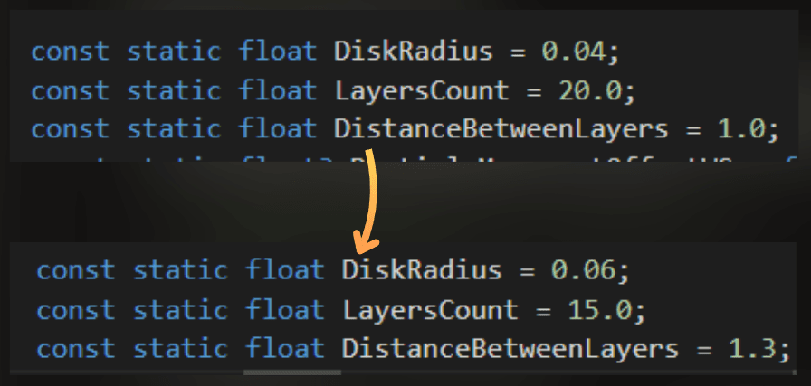
Before:
After:
And it got faster. From 0.45ms to 0.35ms.

___
5th optimization iteration - baking the particle positions
To be honest, I was sure that at this point I would cut the time of this effect by half compared to the first profiling, but I'm not giving up. I need to shave just 0.05ms to achieve that! And I have an idea!
I could render particle positions into a texture in a separate render pass.
Currently, the particle position is calculated for each rendered pixel, while it could be prebaked into a texture and calculated once per cell.
My idea is to render a 64x64 texture where each pixel will contain the baked particle position. This would allow me to completely skip the particle position calculation in the particle shader code.
So I created a renderer feature that bakes this texture each frame. I used URP's render graph:
public override void RecordRenderGraph(RenderGraph renderGraph, ContextContainer frameData)
{
var resources = frameData.GetOrCreate<ParticleBakingResourceData>();
TextureDesc desc = new TextureDesc(64, 64)
{
name = "ParticleBakingTexture",
colorFormat = GraphicsFormat.R16G16_UNorm,
clearBuffer = true,
clearColor = Color.clear,
filterMode = FilterMode.Point,
wrapMode = TextureWrapMode.Repeat
};
resources.bakedTexture = renderGraph.CreateTexture(desc);
using (var builder = renderGraph.AddRasterRenderPass(nameof(ParticleBakingPass), out PassData passData))
{
builder.AllowPassCulling(false);
builder.SetRenderAttachment(resources.bakedTexture, 0, AccessFlags.Write);
builder.SetGlobalTextureAfterPass(resources.bakedTexture, Shader.PropertyToID("_BakedParticlesData"));
passData.material = material;
builder.SetRenderFunc((PassData data, RasterGraphContext context) =>
{
context.cmd.DrawProcedural(Matrix4x4.identity, data.material, 0, MeshTopology.Triangles, 6, 1
And I baked the particle positions using this shader:
const static float DiskRadius = 0.05;

float4 frag(FragmentData input) : SV_Target0
{
	float2 cellIDHash = FastHash2_2(input.uv * 3.489712);
	float2 diskCenter = cos(_Time.yy * cellIDHash * 2.0) * 0.5 + 0.5;
	diskCenter = lerp(DiskRadius, 1.0 - DiskRadius, diskCenter);

	return float4(diskCenter, 0.0, 1.0
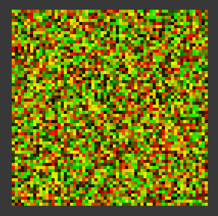
This is how this texture looks. In the RG channels, it encodes the position of each particle:
The texture looks like colored noise. Red channel = X position, Green channel = Y position. Each pixel represents one particle's position within its cell.
Then, when rendering the particles, instead of recalculating the position, I just sample the texture:
float2 cellID = floor(uv);
float2 cellUV = uv - floor(uv);
float2 diskCenter = _BakedParticlesData.SampleLevel(pointRepeatSampler, cellID * bakedDataTexelSize.xy, 0.0);
float disk = DrawDisk(cellUV, diskCenter, DiskRadius
float2 cellID = floor(uv);
float2 cellUV = uv - floor(uv);
float2 diskCenter = _BakedParticlesData.SampleLevel(pointRepeatSampler, cellID * bakedDataTexelSize.xy, 0.0);
float disk = DrawDisk(cellUV, diskCenter, DiskRadius
float2 cellID = floor(uv);
float2 cellUV = uv - floor(uv);
float2 diskCenter = _BakedParticlesData.SampleLevel(pointRepeatSampler, cellID * bakedDataTexelSize.xy, 0.0);
float disk = DrawDisk(cellUV, diskCenter, DiskRadius
Results:
The time reduced from 0.35ms to 0.27ms. This is a significant improvement at this point.
And rendering the texture with baked particle positions takes ~0.032us (0.000032ms). It was actually hard to find it in the profiler. When I count the empty space around this performance marker, it would be closer to 0.0004ms.
This is how the final effect looks.
___
Summary and key takeaways
In this article, I showed how to create 3D snow particles using only fragment shaders. Here are the key techniques:
Grid-based particle placement
Multiple raycasted planes to create volumetric depth
Smooth fading to hide plane boundaries
Performance optimizations:
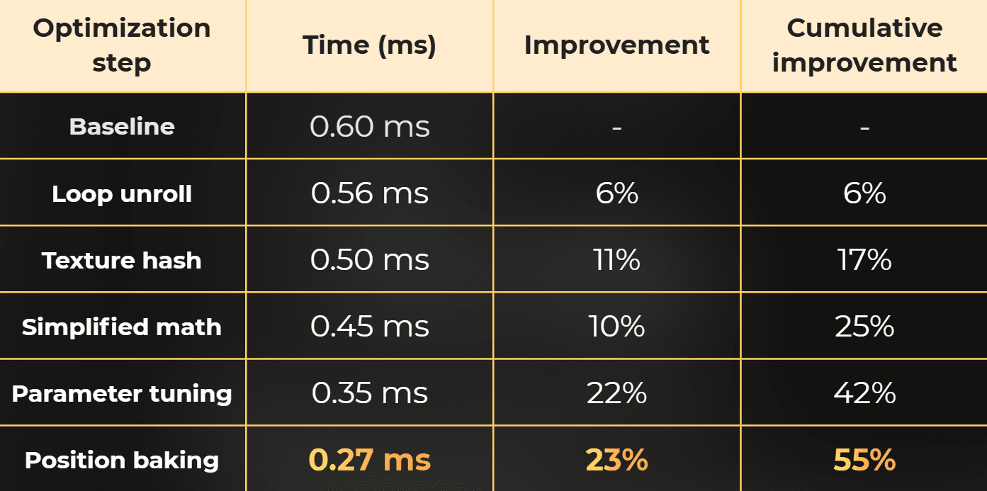
0.27ms per frame (started at 0.60ms). That's a 2.2x speedup.
Limitations:
Particles are displayed on aligned planes, so they work only for a specific camera angles.
They are rendered fullscreen - always.
Fixed particle density.
It is more like a ShaderToy gimmick and nice graphics programming practice than a feature that you would use for production.
In production I would use it for UI particles
The full shader code is available on ShaderToy: https://www.shadertoy.com/view/WcGfDz
Optimized code for Unity: FragmentShaderParticles.unitypackage
You will also like (with optimization case studies):
Stateless particles - rendering without a mesh
:center-px:
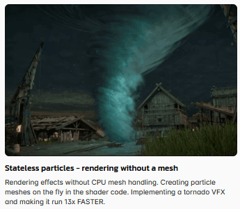
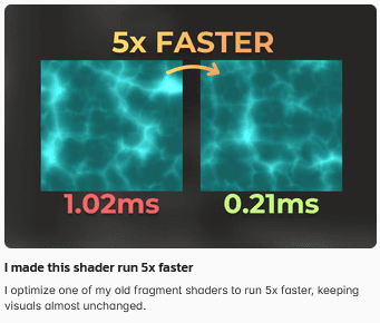
I made this shader run 5x faster
:center-px: