Tech-Art
Intermediate
Deep dive
The nature of the pixel
10 min

In rendering, I spend a lot of time fighting with the nature of the pixel. Many problems in the rendering are not really about lighting, materials, or even shader code itself. They happen because the final image on the screen is not continuous. It is made of pixels. And the GPU needs to decide what color each of those pixels should have. Here, I want to explain how this affects shape rendering, antialiasing, texture sampling, mipmaps, anisotropic filtering, raymarching, temporal antialiasing, and even tiny UI details like small icons.

___
Screen image is discrete
It is easy to think about an image on the screen as if it was continuous. In fact, a lot of shader programming can be done by assuming that the image is continuous, and most things will still work.
But the truth is that the screen is just a grid of points. Each pixel stores one value, usually color.
That single fact creates a lot of visual problems in practice:
hard jagged edges
shimmering textures
unstable tiny details
UI icons that look great at one position and bad after moving by half a pixel
When I think about rendering, this is one of the things I keep in mind: the final image is sampled into a discrete grid.
To make the article easier to follow, I will use pixel for the screen grid and texel for the texture grid. They are closely related, but they are not the same thing.
___
Fragment shader evaluates at the pixel center
Now, here is the next important detail.
When a fragment shader runs for a pixel, it does not evaluate the whole square area of that pixel. It evaluates at a sample location. In the simplest mental model, that location is the pixel center.
So if I render an analytical shape in the fragment shader, the question is:
"What is the value of my shader function at the center of this pixel?"
For example, the simplest way to render a circle:
This shader does not care if a pixel is mostly covered by the circle. It only checks one point. If the evaluated point is inside, the pixel is white. If not, the pixel is black.
So the result is a grid of binary decisions that approximates a circle. What allows us to perceive it as a circle is the density of the pixels on the screen, which is affected by the screen resolution and its physical size. Below you can see a circle rendered at different resolutions:
___
The issue: aliasing on shapes
Some pixels near the edge are fully white, some are fully black, and there is no middle ground. That creates jagged edges. This is especially visible on slowly moving shapes.
This is aliasing in its most basic form.
So how do I fix that?
___
First antialiasing path: multiple samples per pixel
Ideally, I could approximate the area of each pixel that is covered by the circle. How can I do that?
The simplest idea is to evaluate the shape multiple times inside one pixel and average the result. Instead of trusting a single sample at the center, I can ask the same question a few times at slightly different subpixel locations.
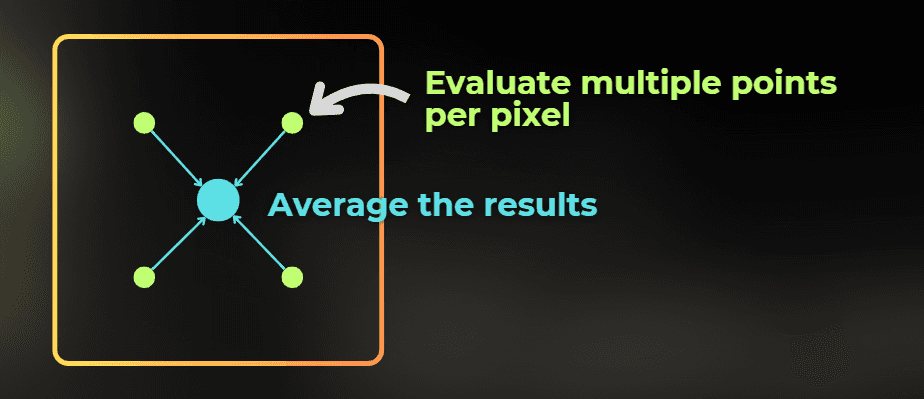
If one sample is inside the circle and three are outside, then the final pixel should not be fully white or fully black. It should be gray. That gray value represents partial coverage of the pixel.
And the interesting thing is that this is very similar to how the MSAA antialiasing method works. It evaluates multiple depth-tests per pixel for triangle edges to estimate the coverage of the pixel - to control its transparency.
more samples per pixel = better estimate of subpixel coverage
There is one important nuance here. Classic hardware MSAA is mostly about geometry coverage and edge evaluation during rasterization. If I render an analytical circle entirely inside a fragment shader, I usually need to reproduce the same idea manually in shader code by evaluating the shape a few times inside the pixel.
To do that in shader code, I need one more piece of information:
How large is one screen pixel in UV units?
Pixel size in UV space
If I want to evaluate the circle at a few subpixel offsets, I need to know how large those offsets should be in the UV domain.
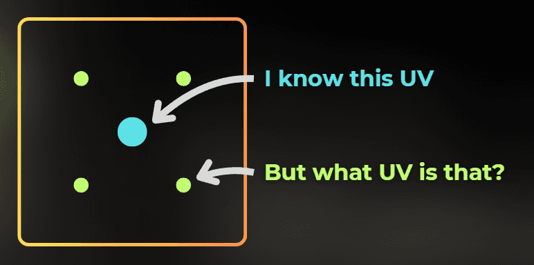
So I need a way to estimate how much UV changes from one pixel to the next one on the screen.
Screen space derivatives
The good news is that the GPU can calculate screen-space derivatives, which describe the difference in an in-shader variable between two neighboring pixels.
Each shader language has functions that let you compute the difference between neighboring pixels. This can be used to calculate pixel size in a specific domain, for example UV space.
This is why pixel shading is organized in 2x2 pixel quads, because you always need to have a neighboring pixel to calculate the derivative.
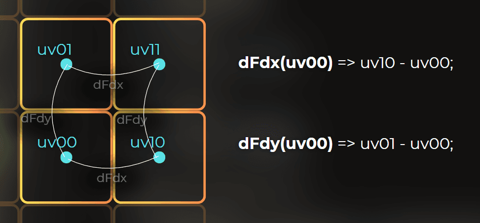
This is what dFdx and dFdy give me:
dFdx(value)tells me how muchvaluechanges between nearby pixels in XdFdy(value)tells me how muchvaluechanges between nearby pixels in Y
Texture sampling uses the same idea to pick the right mip level.
And this is the bridge to texturing: the same derivatives that tell me how large one screen pixel is in UV space also tell the GPU how large the texture texel is for that pixel.
So to render a circle, I can just calculate more samples. I will calculate the pixel size by using this formula.
Very simplified version for non-rotated, non-skewed UVs:
Note that the above formula only works if the UV axis is aligned with screen space, without any rotation or skew. If the UV is transformed in some way, you may need a different way to calculate pixel size. For example, this gives me a useful scalar estimate of how large one screen pixel is in UV space:
Then, using this, I can evaluate the circle at four different UV positions to implement antialiasing:
And this is how it looks:
I could also increase the number of samples to 16. The more samples I use, the more accurate the result becomes, but it also gets more expensive to compute.
___
Second antialiasing path: analytical
There is another way to fight the aliasing, and for analytical shapes this one is elegant. While the previous methods solve the problem by using "MORE SAMPLES", this one is entirely analytical, but it only works for specific use cases.
Instead of evaluating the shape as a binary inside/outside test, I can evaluate a signed distance field.
A signed distance field returns the distance to the closest surface:
negative inside the shape
positive outside the shape
zero exactly on the edge
I like SDFs because they turn edge antialiasing into a very local problem. If I know the signed distance and I know roughly how wide one screen pixel is, I can smoothly interpolate the coverage at the edge.
For a circle, the SDF is simple:
Example: https://www.shadertoy.com/view/3ltSW2
I can draw a circle using SDF's like this:
And when I shrink the fade width and keep it exactly at pixel size, notice what happens:
I can render the antialiased circle like this:
One distance evaluation = smooth edge. You can see it happen here, in the demo shaders:
Visualization: https://www.shadertoy.com/view/fc23WR
Antialiased circle: https://www.shadertoy.com/view/Nc23WR
No manual 4x or 16x sampling is required. For analytical shapes - this is usually my favorite solution.
___
Why SDF antialiasing is so useful
SDF antialiasing is used in:
fonts
vector shapes
icon rendering
SVG rasterization
Of course, it works best for analytical or distance-field-based content. It is not a universal answer for every kind of aliasing. But for shapes, text, and clean vector-like forms, it is hard to beat.
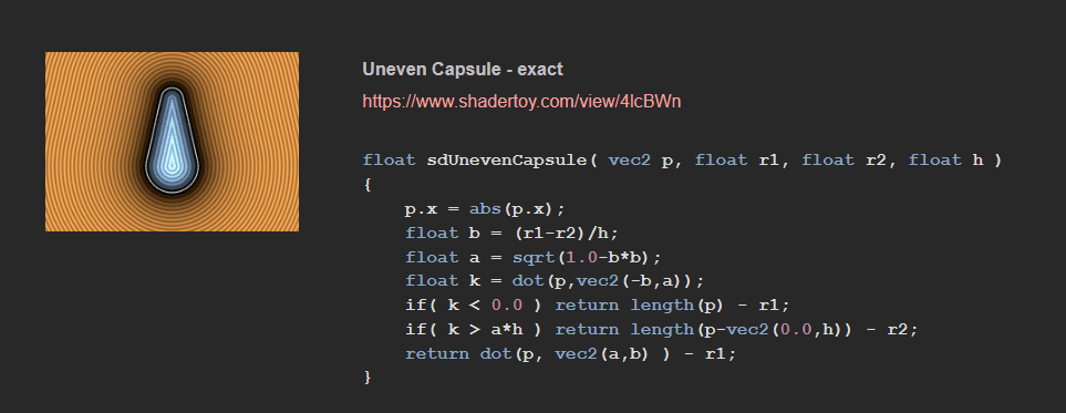
You can find more SDF functions here:
https://iquilezles.org/articles/distfunctions2d/
___
Texturing implications
Now let's see how the discrete nature of pixels affects texture sampling.
Textures are stored as a grid of texels, and they need to be rendered into a grid of pixels. So when thinking about texture sampling, there are two sensitive places in the pipeline: reading from the texture and writing to the screen.
Let's say I want to texture a plane. The first problem is that the texture is stored as a grid of texels, so if I just pick the nearest texel to sample, the image will look like this.
This is why we need texture filtering when sampling a texture. Bilinear filtering, for example, interpolates four neighboring texels together. So you figure out the four closest texels and then interpolate them linearly:
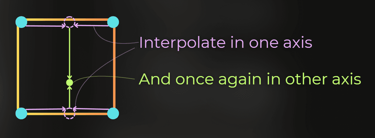
The same data sampled using bilinear interpolation:
There are two other filtering methods supported in hardware:
trilinear filtering - does bilinear filtering for two mipmaps and interpolates between them
anisotropic filtering - in a simplified mental model, it behaves a bit like taking several texture samples for one pixel in a more direction-aware way, so angled surfaces stay sharper without bringing back too much shimmer
But after I sample the texture, it needs to be projected to the screen. Imagine that the above texture needs to be projected onto the pixels marked in red:
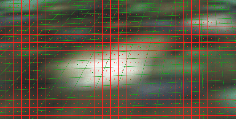
Let's visualize that. Green lines and dots represent texture texels, while the red lines and dots represent the screen pixels.
Now, notice what happens when the texture texel density is much higher than the screen pixel density:
With high texel density, there is a lot of shimmering, because after a slight camera movement, a screen pixel may pick a very different texel from the texture. You can see it yourself using this Shadertoy example: https://www.shadertoy.com/view/7fS3W1
Also, if screen pixels sample texture data that is far apart in memory, it lowers the cache hit rate. So sampling textures at unnecessarily high resolution can be very inefficient for the GPU.
This problem is solved by mipmaps. Mipmaps allow us to store different versions of the same texture in VRAM, each one with a different resolution. Then the GPU can pick the right version, so the resolution of the sampled texture better fits the screen pixel density. Adding a mipmap chain to a texture usually adds about 30% to the memory usage, but the visual improvements and sampling performance are usually worth it.
The GPU uses screen-space derivatives to calculate pixel size in the UV domain and determine which mipmap LOD to use. It tries to pick the mipmap whose texel density is close to the screen pixel density.
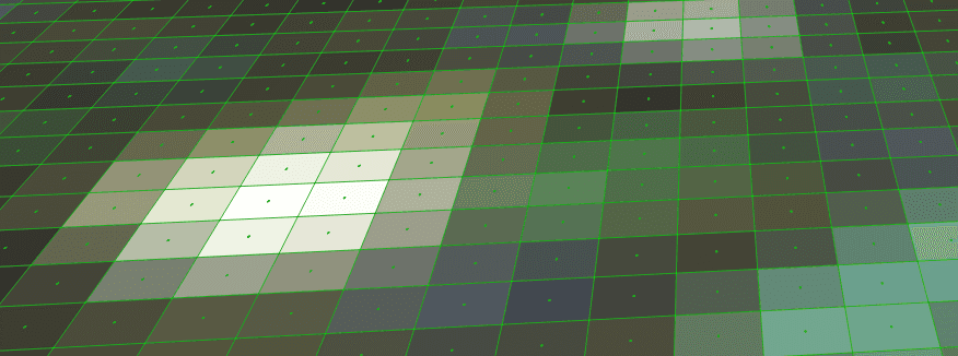
Now the problem is that many textures viewed at a steep angle look blurry. That happens when the GPU decides to pick a mipmap that is too coarse:
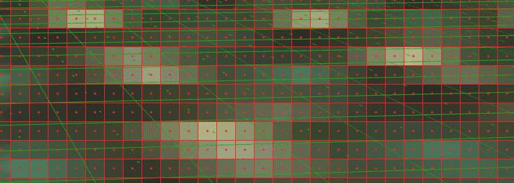
This is solved by anisotropic filtering. The simplified mental model is that it samples a higher-resolution mipmap multiple times per pixel in a direction-aware way. That is only an approximation of what is happening underneath, because the actual hardware implementation can get more complex and is implementation-dependent.
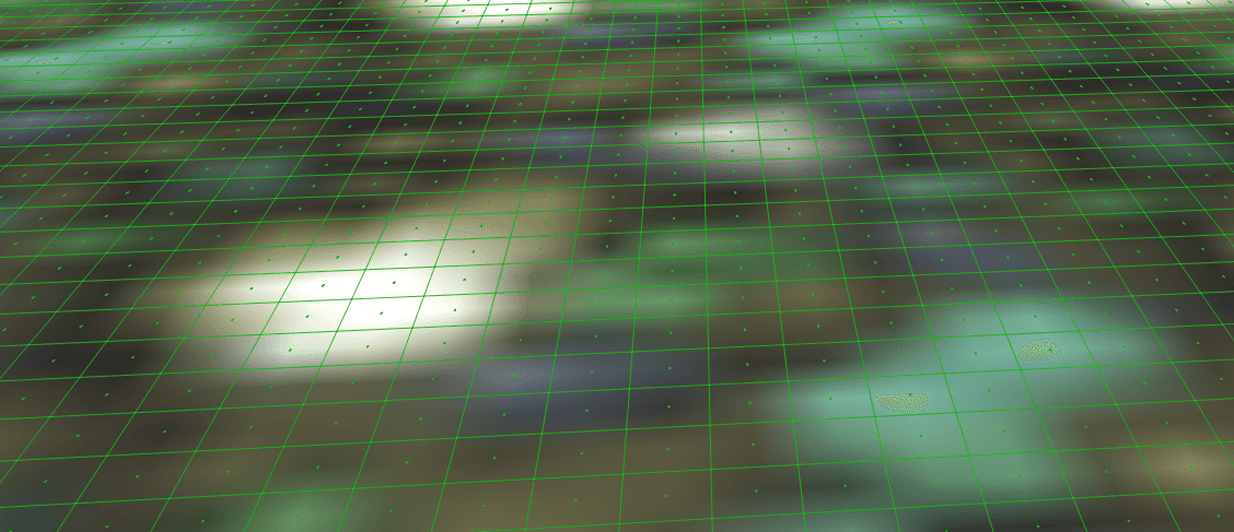
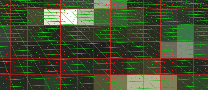
Anisotropic filtering could be approximated this way: sample a higher-resolution mipmap several times and average the result for one pixel. In the image below, green dots represent texture texels and red dots represent sampling positions.
If you want a concise and more technically accurate explanation, this OpenGL tutorial page is a good reference:
https://paroj.github.io/gltut/Texturing/Tut15%20Anisotropy.html
And this is how anisotropic filtering can improve texture quality.
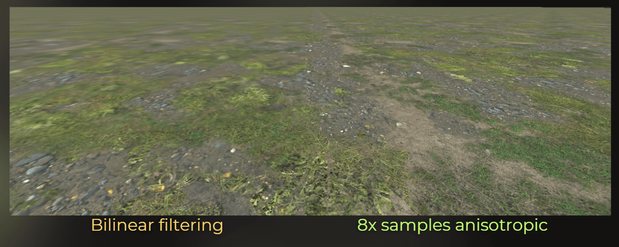
So with bilinear/trilinear filtering and mipmaps, we can battle the shimmer.
With anisotropic filtering, we can fight the blur.
___
Raymarching, parallax mapping, and texture loops
This same pixel-vs-texel problem shows up in techniques that sample textures in a loop, such as parallax mapping or some raymarching-like effects done in screen space.
The issue is that texture LOD is chosen from screen-space derivatives taken from nearby pixels. But once each pixel starts walking through the texture in a slightly different way inside a loop, the implicit LOD choice can stop matching the actual texture footprint. That can create visible 2x2-like artifacts, shimmer, or unstable detail because neighboring pixels no longer agree on what mip level should be used.
This usually appears during raymarching, if you don't calculate LOD levels on your own.
___
Temporal antialiasing
Temporal antialiasing is also fighting the nature of the pixel, just in a different way.
TAA relies on motion vectors and reprojection, which means it reuses information from previous frames and blends it with the current one. To do that, it has to interpolate pixel data across time and space. That is why TAA naturally tends to make the image more blurry, even though it does a great job at reducing shimmer and subpixel flicker.
Source: https://www.reddit.com/r/thefinals/comments/18rm4l1/example_of_why_taa_is_bad_blurry_finals_forces/
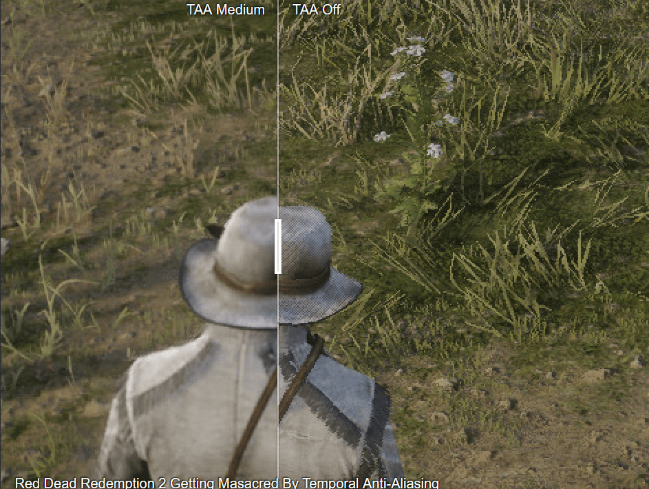
So once again, the tradeoff comes from the same place: we are trying to reconstruct a stable continuous image from a sequence of discrete pixel samples.
___
Practical example: small UI icons
Now let's move from theory to one of my favorite practical examples. This is something I faced in production while working with a UI designer. We wanted to render very small but sharp icons in Unity.
Imagine I have a 64x64 icon texture, but on the screen I render it in different areas that can range from 14x14 pixels to 34x34 pixels because the UI scales with screen resolution.
:center-px:
Now, let's render the icon in the UI. This is the default Unity shader that renders the icon into a 21x21 square on the screen:
:center-px:
And this is the zoomed-in version:
:center-50:

And it looks really awful in motion:
First issue: Too sharp
:center-px:
At some resolutions, the texture appears too sharp, which becomes visible during movement.
This is because the texture has mipmaps disabled by default. So I enabled mipmaps.
Second issue: Too much blur
:center-px:
It seems like the GPU is picking a very coarse LOD. I decided to create a shader that applies an LOD offset to the mipmap, telling the GPU to pick a sharper image. I used Shader Graph.
I used the Calculate Level Of Detail node to get the current LOD, then applied a bias to that value and used it to sample the texture.
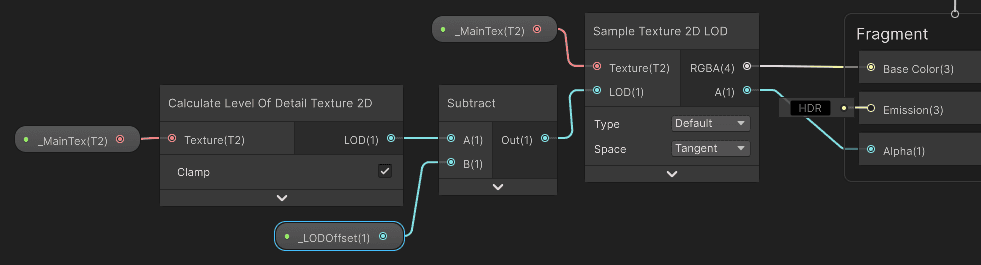
Now, the movement of this icon looks much better:
Third issue: symmetry
Now, the last issue that was bothering me was symmetry. The icon is symmetrical, but it does not look properly symmetrical in this case. In the previous section of the article, I described two sensitive places to check here: texture encoding and screen-grid alignment.
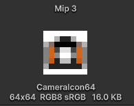
Symmetry can break when the icon is not perfectly centered in the original image, because that can lead to asymmetrical mipmap generation. So I checked the mipmap levels.
:center-px:
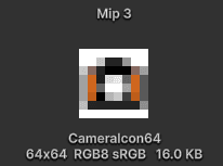
And it looks like something went wrong during mipmap generation. After further inspection, I noticed that the icon is not perfectly centered in the original file, and that breaks symmetry in the mipmap chain.
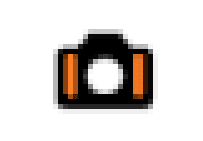
So I jumped into the best image-editing program and moved the icon to the center.
Now the mipmap chain is symmetrical:
:center-px:
I checked the icon rendering, and it still does not look quite right:
:center-50:
The other thing to check is whether the texture texels are aligned with the screen pixels. I need to do one more thing: snap the icon's symmetry axis to the screen pixel center or pixel edge. I can do this in a custom shader or a component.
Now, the movement rule is this: when the icon is moving, it is completely free. But when the movement stops, its vertical axis is snapped to the pixel center or edge:
:center-px:
Compare it to the original one. What an awful pixel abomination.
And this connects back to the main thesis of the article: even such a simple thing like icon rendering can be easily messed up if you don't care about the nature of the texels and pixels in rendering.
:center-px:
___
Summary
This is the core idea I keep in mind:
The screen is not continuous. It is a grid.
Fragment shading is evaluated at sample positions, not over the full pixel area.
A hard analytical shape rendered with one sample per pixel will create aliasing.
Multiple samples per pixel improve coverage estimation, but they cost performance.
SDFs are a much cleaner way to antialias analytical shapes.
dFdx,dFdy, orfwidthin GLSL tell me how fast values change between nearby pixels, which lets me estimate pixel size.The GPU uses the same idea to choose mipmaps when sampling textures.
Mipmaps solve a lot of texture shimmer, and anisotropic filtering improves the result at steep angles.
Tiny UI details often look best only after filtering, mipmaps, and pixel-grid alignment are all handled carefully.